#L298N MOTOR DRIVER TUTORIAL DRIVER#
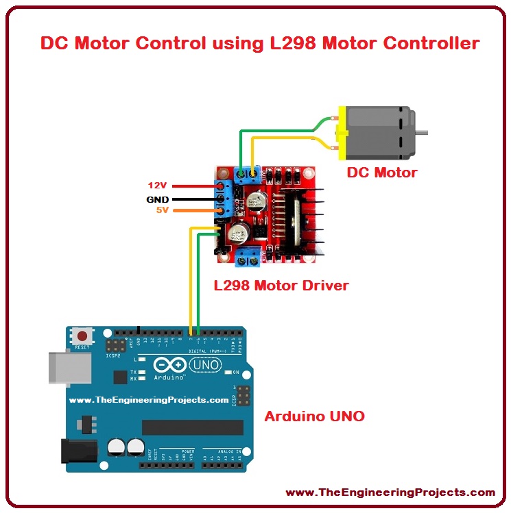
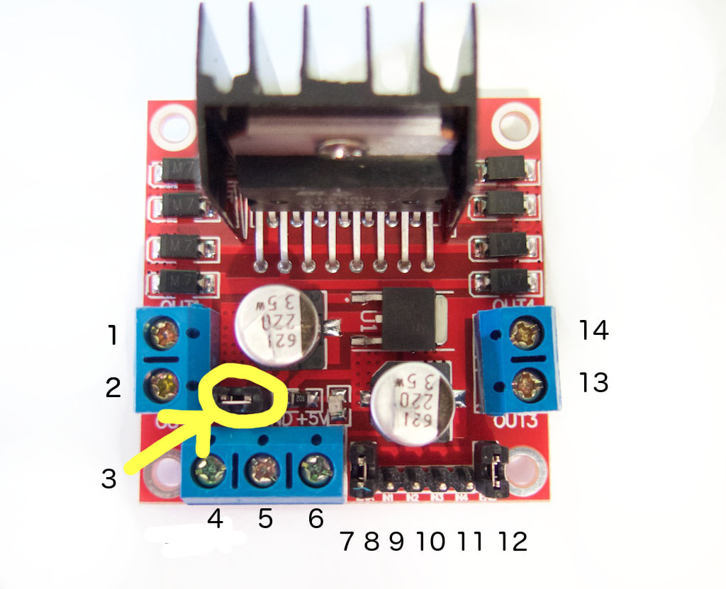
So, with the Functionality of both L298N Motor Driver Module as well as Joystick Module, we can control the two DC motors at the same time./* * This ESP32 code is created by esp32io. Here, we will make both the motors work simultaneously but not back and forth on each axis. The Joystick Module allows one motor to go back and forth on one axis. There is also an onboard 5V regulator, so if your supply voltage is up to 12V you can also source 5V from the board. The L298N Motor Driver Module allows you to control the speed and direction of two DC motors, or control one bipolar stepper motor with ease. The L298N H-bridge module can be used with motors that have a voltage of between 5 and 35V DC(Power Supply). In this project we used L298N Motor Driver Module to connect the motors and also control the direction of the motors using Joystick Module. Welcome to the Arduino Based Project which consists of L298N Motor Driver Module, Joystick Module and DC Motors. Connect the 5V Output to the external power supply ( Battery Power Supply). Connect the Pin Driver Power Input to Arduino Uno 5V Pin, Connect GND Pin of L298N Motor Driver Module to the Battery GND and Arduino Uno gnd. signal affect the internal logic circuit portion to operate at a low voltage. Now, connect the supply to L298N motor driver. On board L298N Stepper Motor Driver with necessary connectors and pinouts. Connect the Arduino Pin 9 to Pin ENA, Pin 8 to IN1, Pin 7 to IN2, Pin 5 to IN3, Pin 4 to IN4 and Pin 3 to ENB of the L298N Motor Driver Module.Connect the two DC motors with the Motor A Output and Motor B Output as shown in the circuit connection. Now we connect the L298N Motor Driver with the Arduino Uno.Connect Joystick GND to Arduino GND, 5V Pin of Joystick Module connects to Arduino 5V Pin, Joystick Pin VRx is connected to Analog Pin A0 of Arduino Uno & Pin VRy of Joystick Module to Analog Pin A1 of Arduino Uno.First, we connect the joystick module with the Arduino Uno.First, we connect the joystick module with the Arduino Uno. Double H driver module uses ST L298N dual full-bridge driver, an integrated monolithic circuit in a 15- lead Multiwatt and PowerSO20 packages.Ground (It grounds Input & Completes circuit)ĥV input (unnecessary if your power source is 7v-35v, if the power source is 7v-35v then it can act as a 5v out)Įnables PWM signal(For Motor Output Enable A)Įnable Motor A (Logic Pins for Motor Direction Control Ports)Įnable Motor B (Logic Pins for Motor Direction Control Ports) This enables power to the on board 5V regulator). Motor B lead out(Negative /For Motor A Output)ġ2V input from DC power source (12V jumper – remove this if using a supply voltage greater than 12V DC. Motor B lead out(Positive /For Motor B Output) Motor A lead out(Negative /For Motor A Output) Motor A lead out(Positive/For Motor A Output) Other extensions: current probe, controlling direction indicator, pull-up resister switch, logic part power supply.Max power: 25W (Temperature 75 Celsius).Enable signal level: Low -0.3V~1.5V, high: 2.3V~Vss.Controlling level: Low -0.3V~1.5V, high: 2.3V~Vss.

#L298N MOTOR DRIVER TUTORIAL DOWNLOAD#
Link to download the software: SPECIFICATIONS JOYSTICK MODULE Jumper wire (Male to female) – 40 pieces eachĪrduino IDE (Programmable platform for Arduino).Jumper wire (Male to male) – 40 pieces each.

Two enable inputs are provided to enable or disable the device independently of the input signal HARDWARE REQUIRED L298N is a high voltage, high current dual full-bridge driver designed to accept standard TTL logic levels and drive inductive loads such as relays, solenoids, DC and stepper motors.


 0 kommentar(er)
